Drumique Analog Drum Machine
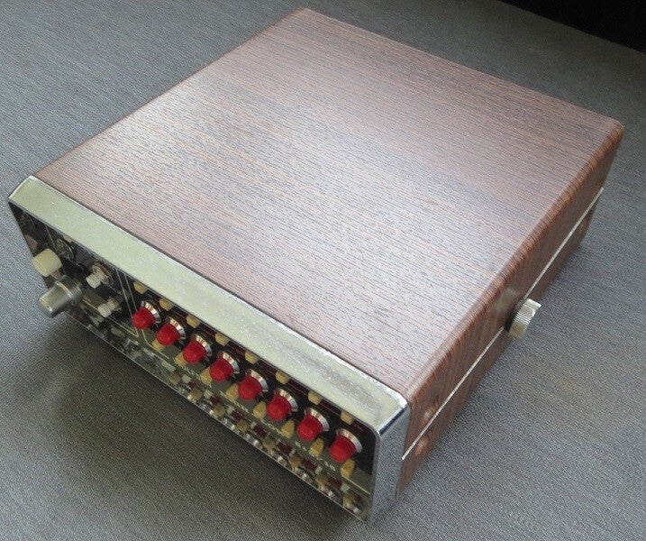
Drumique uses fully analog circuitry to generate it's four sounds: kick, snare, high hat and claps.
These analog circuits receive their triggers from an Arduino, which acts as the brains of the unit. It features a 16-step sequencer and each step for each sound can be set through the front-panel switches.
Video can be found here.
Please note that this page is a work-in-progress, as I have a lot of ground to cover on this one. Be patient please :)
The Brains
The thing that is at the center of it all: the Arduino. It reads out the front panel controls, receives MIDI data and converts it all to 4 triggers which are send to the 4 analog circuits to generate dem tasty beats!
At first I wanted to use an interrupt for the timing, but decided that this was overkill really and just stuck with using Micros() to time stuff. This is more than precise enough and well... can always easily change it, that's the advantage of the Arduino :)
Here's two great macros I made for the SQK-1 project to use instead of the DigitalRead and DigitalWrite functions. These will give you up to 40 times more speed!
//DigitalWrite does a lot of error checking (pin correctly set etc) which this obviously doesn't, so make sure your code is correct!
//'x' is the port (for example: PORTB)!
//'y' is the port number, not the pin number!
#define CLR(x,y)(x&=(~(1<<y))) //equalivent to: DigitalWrite(pin, LOW);
#define SET(x,y)(x|=(1<<y)) //equalivent to: DigitalWrite(pin, HIGH);
Notes:
I'm planning to replace all the slow Arduino library functions with faster stuff, such as direct (bitwise) port manipulation, but for clarity's sake I've kept the Arduino library functions in the code below. This code hasn't had any optimizations either, again because of clarity.
Don't worry though, it will run just fine (this exact code was running on Drumique in the demo video).
I'm using two CD4022 decade counters to scan the front panel controls. The Arduino generates clock and reset signals to make the CD4022's iterate through all the buttons through diodes (to prevent crosstalk and false signals). In turn all the buttons are connected to two connections which go back to the Arduino.
If a button is pressed this connection will be pulled high when the CD4022 switches on the output it has that button connected to and thus the Arduino knows that that button is pressed. This system reduces the amount of connections from 20 to a mere 6 :)
You can download the code here.
The Kick Drum

The kick is build around a bridged-T circuit, using a 4558 or 358 op-amp. Other similar op-amps will probably work too though you might get varying decay times and pitches.
The supply voltages are a bit odd because this circuit is most happy with a dual rail power supply. Since I only had a 12V single rail supply available I simply made a virtual ground using an op-amp as a buffer, V+ is +6V and V- is -6V in my schematic. Note that the trigger filter and bridged-T circuit both use the virtual ground.
The reason I used this circuit and not a simple resistor-divider is because using an op-amp you get way more stability even if the current draw is higher. A resistor-divider shifts in voltage as soon as you get a couple of mA of current draw and this would affect the sound.
I'm glad I ended up doing it this way because I ended up using that 6V/virtual ground quite a few times!
The Snare Drum

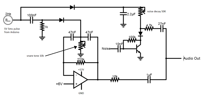
The snare combines a classic transistor noise circuit through a simple VCA and the bridged-T circuit. The idea is that the noise emulated the snare mat, whereas the bridged-T circuit emulates the drum sound itself. Note that the bridged-T uses the virtual ground discussed earlier (here at +6V relative to actual ground!).
In all honesty it sounds a bit more like a noisy tom, but since the Drumique already had the harch claps sound this turned out to be a perfect "snare" for this sound set. So I kept it the way it is.
Some analog drum machines run the noise through the bridged-T instead of having it separate, which sounds a bit harsher than what my circuit generates.
Experimentation is key so try both ways and see what you like! I also suggest using trimmers instead of the two output resistors to fine tune the mix between tone and noise.
The noise circuit I've used in all my noise circuits (snare, high hat and claps) is the one by R. Andersen.
You can see it in the image to the left. It's a very classic type of circuit but very effective!
Please note that in my snare circuit the 4.7k resistor is replaced by the diode of the VCA and that I used different values for the resistor and capacitor.
The High Hat

The high hat is quite a complex circuit. Just like the snare drum it consists of two main sounds mixed together.
In this case it's three square wave oscillators that are tuned to frequencies quite close to eachother. This mimics the way a real cymbal resonates, generating loads of overtones and harmonics. Since square waves have a lot of harmonics they are a great solution to emulating a cymbal.
Again it's a good idea to use a trimmer for the noise mix (22k resistor) as certain settings generate various kind of tones and vibes, so its great to tune this sound to your liking.
The noise circuit used is the same one as the snare, but again with slightly different values.
The Claps

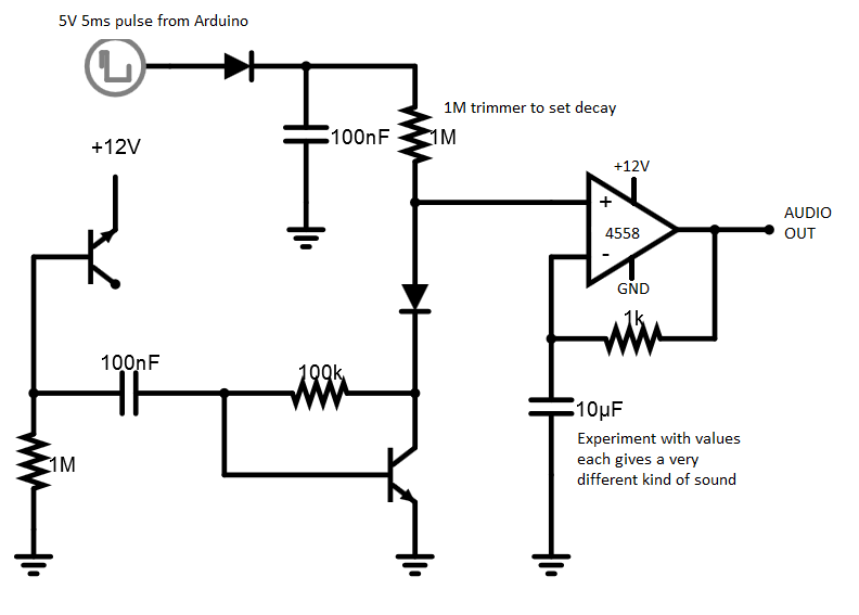
The claps are actually just really op-amp distorted noise, but despite its simplicity it sounds great. The decay setting matters a lot for the sound, can go from very snappy and short (almost snare) sounds to lengthy and gnarly. The capacitor in the op-amp circuit matters a lot for the sound so my advice is to play around with different ones on your breadboard.


