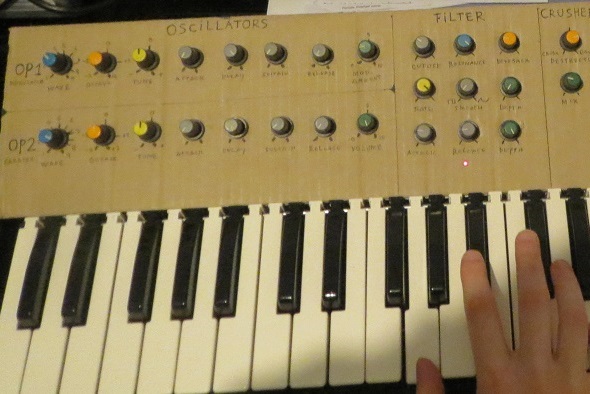
The SQK-01 prototype
This was my first synthesizer project in ages and this prototype is still one of my favorite synths to use in the studio. Well except that it's in pieces now because parts haha
It uses an Arduino Mega for the controls and for the FM Synthesis. Needless to say I squeezed every clock cycle out of the poor Atmega processor but
it was great fun to do so! The Arduino's output signal goes through several analog circuitry such as an VCF and distortion.
You can find the demonstration video
here.
I've also made a VST plugin version which you can find
here. This plugin is based on the final version of SQK-01, not so much this prototype.
This page is unfinished and I'll probably never bother to complete it as this was just an idea prototype. The final version of SQK-01 uses entirely different hardware and thus
will have its own page!
The Digital Part
There's a LOT of code in this project so I'm not going to put it -all- on this page, just snippets to go along with my explanation.
The Arduino project files can be downloaded
here.
I advice you to have a look at the project files first so you can get a general idea of the structure.
This code is obviously outdated now as I'm working on a final version of the SQK-01 (the one this page is about is just a prototype!). This final version will
use an Arduino Due for more power and better audio quality as well as my improved Twin-T circuit design. I also have a neat stereo chorus design and a rather expensive reverb circuit that I'm going to implement in this final build.
The user interface is also -much- better, with knobs, buttons with indicator lights and a 3-digit seven segment display.
The Analog Part

I think this is the circuit topology I used for the filter and AR envelope. It's a Bridged T resonant filter, one of my favorites.
Stupidly, my collection of schematics for the SQK-1 are a mess, so I need some time to
make everything neat, updated and sorted out. I do think this could work, though I'd use 100k to 1M resistors instead of 10k on that transistor
base. Op amp is powered by 12V single rail, hence the resistor-divider on the non-inverting input to act as a virtual ground at +6V.
The LFO is a simple 40106 oscillator, with a simple passive low pass as an integrator to get a sort-of-triangle-ish-waveform.
Copyright 2018 Evil Turtle Productions. All Rights Reserved.